An Introduction to High Performance Network Connectivity
Executive Summary
Recent years have experienced a rapid deployment of virtualized computing and adaption of cloud environments. Modern data center networks have evolved very quickly to keep up with the changing pattern of their workloads – moving away from client-server traffic towards server-to-server workloads. This transformation from legacy to cloud data centers is consistently elevating the importance of the physical network of the data center. If a link to a physical server does not deliver the required performance, this factor also affects all the virtual machines running on the server and its applications.
This paper explains the impact of packet loss on application performance and why the cabling plant, besides the routers and switches, is a major influencing factor on throughput and latency. Based on the understanding that conventional power-loss measurement methods cannot deliver all the necessary information about link performance, R&M, in partnership with Xena Networks, conducted performance benchmark tests for R&M’s High Performance Network Connectivity (HPNC).
The outcome validated the combination of R&M’s MTP® cabling system and Finisar’s QSFP+ parallel fiber-optics module to enable a “zero packet loss” 40G Ethernet extended-reach solution. R&M specifies 330m over OM3 cabling and 600m over OM4 cabling, each with four MTP®[1] connections in between. This innovation means that the data center industry can more easily serve distances beyond the 100m OM3 and 150m OM4 currently specified in the IEEE 802.3ba 40GBASE-SR4 standard.
The New Type of Data Center Network
Data centers are indispensable control centers of business opportunities in cloud, mobility and big data today. With their databases, data storage systems and applications, they are the nerve center of all key business processes. Not many years ago, the majority of total computing power was wasted due to underutilized server capacity. The concept of virtualization was introduced to fight this waste of resources, and entails the need to optimize both performance and costs as well as increase business agility. Investment costs could be lowered by reducing the number of physical machines allocated to a specific application. At the same time, every virtual machine needs the same bandwidth as a physical server prior to its virtualization. That is why the bandwidth requirements of a virtualized server rose proportionally to the number of its virtual machines.
In the meantime, this transformation from legacy to cloud data centers is consistently elevating the importance of the physical network. If a link to a physical server does not deliver the required performance or even fails, this factor also affects access to all the virtual machines running on the server and its applications.
Packet Loss – The Performance Killer
Data center networks have evolved very quickly in recent years to keep up with the changing pattern of their workloads – moving away from client-server traffic towards server-to-server workloads. This transition requires intensive communication between end-hosts across the data center network. In this environment, today’s state-of-the-art TCP protocol falls short.
TCP works on an acknowledgement basis. The receiving computer has to acknowledge correct reception of data back to the server within the TCP Receive Window size. Unfortunately, TCP, delay, and Window size are all impacted by packet loss and the fact that even a small percentage can significantly reduce throughput in data center networks.
Assuming a server with a 10G NIC, a 10G Ethernet network with three hops, and another server also with a 10G NIC. The application is going to transfer some data using following TCP settings:
- Bandwidth = 10Gbps
- TCP Windows Size = 375 kBytes (not unrealistic for enterprise class networks)
- Maximum Segment Size = 1460 Bytes
- Delay = 0.3 ms RTT
With these settings, the throughput fully utilizes the underlying 10G network. If now only 0.1% of the packets are lost, the throughput drops to just 1Gbps – a tenth of the actual network bandwidth! [1]
Thus, with the new workload pattern came an often seen phenomenon of slowly performing SAP and database applications, or Citrix sessions getting stuck.
Traffic in the Data Center
Today, there are three types of traffic within a data center. The first one is the conventional application traffic which is steadily growing. The second type is called inter-process communications. This kind of traffic is driven by distributed systems used for virtualization and cloud computing. And finally, there is storage traffic – shooting up due to the proliferation of networked storage.
Each of these types of data traffic has a differing tolerance for packet loss, delay and jitter. Service Level Agreements (SLAs) dictate certain performance criteria that have to be met. Most of them document values such as network availability and mean time to recover (MTTR), which can be easily verified. However, performance criteria for Ethernet and Fiber Channel are more difficult to verify. A simple Ping command cannot precisely depict inquiries about performance, data throughput, packet loss and service integrity.
How the Physical Network Influences Application Performance
The question stands why packet loss has such a drastic impact on application performance. One reason is found in the way TCP handles packet loss. If the receiver does not confirm a sent packet within a given period, the sender will retransmit it. This time span is known as Retransmission Timeout, and usually lasts for 500 ms to 3 s, with exponential backoff as more timeouts occur. This comes from a time when TCP was solely used to enable communication across a WAN. However, in today’s data centers this period exceeds usual round-trip times (RTT) by orders of magnitude. The consequences are worsening response time and performance.
In an environment of virtualized desktops, the loss of packets and herewith the increase in Retransmission Timeout, can lead to response times of the system on user input of more than a second. Most users would consider this amount of delay as unacceptable.
Packet loss can occur for several reasons:
a) Congestion.
b) Proactive flow control schemes to avoid congestion.
c) Faulty routers or switches.
d) Bit errors.
The TCP protocol assumes that all packet loss is caused by congestion. But what is often forgotten is the fact that poor physical connectivity significantly reduces the network performance by causing a high number of bit errors and packet loss. Figure 1 depicts the fundamental chain of cause and effect with the network.
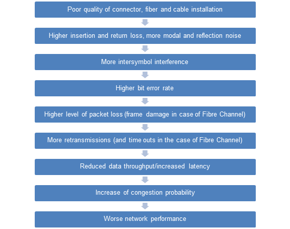
Figure 1: Chain of cause and effect, linking connectivity quality with network performance
When analyzing the influence of the physical network on application performance, it all starts with the quality of the individual components – that is connectors, adapters, and the cable including the fiber – as well as that of the installation. To cover all aspects of component and installation quality would fill volumes of heavy-weight books. Therefore, only two aspects shall be mentioned at this point, namely the endface geometry of connectors and a proper installation training.
The resulting performance of fiber optic connectivity strongly depends on its mechanical characteristics which are given by the geometry and determine both alignment and physical contact of fiber cores. For this purpose, a 100% quality control of fiber and connector endfaces has to be a prerequisite. But the best components are void if the installation quality does not meet its needs. Hence, only highly competent experts trained and supported by the top-notch vendors of physical network infrastructures can assure that all products are installed and tested according to the latest standards and best practices.
It is well known that insertion and return loss are fundamental parameters which are influenced by those aspects mentioned above. Technicians test permanent links and channels to check whether they will stand the projected network requirements. However, conventional measurement methods are not delivering all the information about channel performance. What is very often overlooked is the fact that individual optical measurements capture and integrate the test signal over a time frame of around 300 of milliseconds, while optical pulses for 10, 40 or current 100 Gigabit Ethernet applications are only 100 picoseconds long – 3,000,000,000 times shorter! It is obvious that these conventional test methods cannot resolve optical phenomena that occur on the bit level such as reflection or modal noise [1]. On the other hand, these sources of noise and phenomena like dispersion can have a very significant effect on the network performance in the form of inter-symbol interference (ISI).
ISI arises from the dispersion of light pulses as the propagate down the fiber. Short, separated light pulses of individual bits spread in time and start over-lapping with light pulses of adjacent bits. This can happen to such an extent that it may not be possible for the receiver to distinguish an 0 bit from a 1 bit, as schematically shown in Figure 2.
Reflection and modal noise as well as inter-symbol-interference will inevitably lead to bit errors. The bit error rate (BER) is a relation between the number of bits that experienced corruption during transmission, and the total number of bits transmitted. A BER of 1 denotes that each bit is corrupted. A BER of 6x10⁻⁶ denotes that six bits are received wrongly on one million bits sent. IEEE 802.3 standards specify BERs of less than 10-12 for 10, 40 and 100 Gigabit Ethernet applications. Fibre Channel applications such as 8GFC or 16GFC are also specified to less than 10-12, in reality however, it is recommended to run these at no more than 10-15.
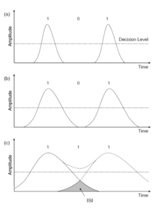
Figure 2: Pulse spreading of a digital (101) bit stream during the propagation in a multimode fiber. The latter case depicts a bit error caused by significant inter-symbol interference (ISI).
If a bit error occurs, the data packet (frame) is damaged and an incorrect frame check sequence (FCS) is detected. Data packets damaged and rendered unusable in this way are discarded and do not take the payload to the recipient. This phenomenon is known as packet loss. The packet loss rate (PLR) is the number of incorrectly received data packets divided by the total number of packets received. The PLR therefore depends on the bit error rate (BER) and the packet size in bits N.
Protocols such as Ethernet or Fiber Channel define packet transmission. Measured variables such as data throughput rate therefore describe the performance of a link.
Data packets consist of frames of fixed sizes, and actual data (payload) of variable sizes. In order to maximize the performance of a network, payload size should be maximized and overhead be minimized. But bit errors may result in a loss of packets which would then have to be re-transmitted. Links with a high bit-error rate are therefore better run with small packet sizes in order to minimize the impact of lost packets. Small packets increase the number of packets transmitted and further burden the network because a larger number of packets have to be switched and because the latency time is increased.
Fiber Channel (FC) applications of a storage area network (SAN) are even more critical. Poor cabling will produce a high number of I/O timeouts or the link will be unstable. An I/O timeout lasts 60 whole seconds in the standard setting. 96 Gigabytes could be transmitted in that time in a 16GFC network. These bit errors may also affect link buffer synchronization (R_RDY). This information indicates that all associated frames that are sent are received, brought into the correct sequence and forwarded to the processor. An R_RDY signal is never repeated, so the Tx stops sending frames until the link is reset. High performing connectivity will minimize the risk of this situation and reduce OpEx for link reset work.
Re-transmission means that the task a packet should fulfill is being delayed. This delay time can entail expensive competitive disadvantageous for many customer segments such as trading business at banks, simulations of a research data center or “Software as a Service” (SaaS) applications in a cloud (e.g.Citrix or SAP). A more efficient network with bigger data throughput and smaller latency also results in higher availability.
With this insight into optical transmission of data, it is evident that a high performing and reliable network is not only determined by switches and routers but is also founded on high performance network connectivity.
Testing
Test Bed
As mentioned before, conventional ways of testing an optical channel, such as power-loss measurements, may not be sufficient to determine the quality of a 40/100G link. To make sure, all relevant information is acquired, real traffic has to be sent over that channel – at best in form of a RFC 2544 test.
All testing was conducted at the R&M Lab in Wetzikon, near Zurich, Switzerland. The test bed included a Xena Networks M2QSFP+ Test Module, two optical modules at the 850 nm wavelength utilizing Finisar 40GBASE-SR4 QSFP+ Gen2 transceivers, and a control and management computer on an out-of-band network. Figure 1 provides an overview of the test bed.
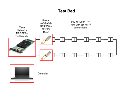
Figure 3: 40GBASE-SR4 test bed employing 600 m OM4 cabling with ten MTP® connector pairs.
How Testing Was Performed
The Xena Networks Test Module ports were connected with each other via two Finisar 40GBASE-SR4 QSFP+ Gen2 transceivers, and a 600 meter channel of multiple OM4 cables of R&M’s High Performance Network Connectivity assortment. These individual cables were interconnected using ten MTP® connector pairs. The built-in Xena2544 RFC test suit from Xena Networks was used to validate the performance of both the transceivers and the R&M OM4 cables over a time span of 16 hours. The same measurement was conducted with a IEEE 802.3 Section 6, 40GBASE-SR4-conform optical channel of 150 meters of OM4 cables with two MTP® connector pairs.
The setup was configured to run RFC 2544 test suites to measure link performance for packet loss and throughput. Packet size metrics were tested to help ensure adequate statistical coverage.
- Packet size (bytes): 64, 128, 256, 512, 1024, 1280, 1518, an 9616 bytes.
Test Results
The following test results were collected:
- RFC 2544 maximum throughput with no loss
- RFC 2544 aggregated frame loss
Figures 4 shows the results.
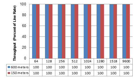
Figure 4: RFC 2544 maximum throughput with 40 Gbps line rate and no loss tolerance for 150 meters and 600 meters OM4 channels.
Also aggregated frame loss tests were conducted for both channel lengths, and no single frame loss occurred over the individual time spans of 16 hours.
R&M demonstrated typical 40G Ethernet 150 m and 600 m distance capability over OM4 fiber with two, ten MTP® connections respectively and randomly selected Finisar 40GBASE-SR4 QSFP+ Gen2 transceivers. R&M’s High Performance Network Connectivity Solution specifies 330 m at OM3 and 600 m at OM4 distances, which is inclusive to the Finisar 40GBASE-SR4 QSFP+ Gen2 transceiver module.
Conclusion
OM4 multimode fiber with MTP® terminations is going to become the dominant connectivity solution in the data center to support 10G, 40G, 100G and future higher data rates. IEEE expectations are that data center links longer than 150 m will become a regular configuration in the near future, covering probably 7% of the 40/100G market [2]. This market requires a low-cost, extended-reach 40G OM4 solution. The combination of R&M’s multimode fiber optic cabling system and Finisar’s QSFP+ parallel fiber-optics module enables R&M to certify an extended reach solution. R&M’s internal testing with a randomly selected Finisar 40GBASE-SR4 QSFP+ Gen2 transceiver modules demonstrated a 600 m distance on R&M’s High Performance Network Connectivity (HPNC) Solution with OM4 multimode fiber that enabled 100% throughput and 0% packet loss over a time span of 16 hours. R&M’s HPNC Solution supports 330 m on OM3 and 600 m on OM4 fiber, which are inclusive to the Finisar 40GBASE-SR4 QSFP+ Gen2 transceiver module.
About R&M
As a global Swiss developer and provider of connectivity systems for high quality, high performance data center networks, R&M offers trusted advice and tailor-made solutions that help Infrastructure and Operation Managers delivering agile, reliable and cost-effective services for a business-oriented IT infrastructure.
R&M’s Convincing Cabling Solutions approach helps organizations to holistically plan, align and converge office, data center and access networks. Its fiber optic, copper and infrastructure monitoring systems ensure the most stringent standards in product quality. Knowing that highest quality products alone are not enough to guarantee faultless operation, R&M works with you on a thorough analysis followed by a structured and forward-looking design of the physical network to provide efficient solutions.
If you are looking for trusted advice and enduring post-sales service – R&M can help.
For additional information, please visit datacenter.rdm.com.
About Xena Networks
Founded in 2007 and based in Denmark, Xena develops affordable, easy-to-use, and flexible Ethernet test solutions. The company's primary focus has been on L2-L3 gigabit Ethernet networking technology and analysis products that deliver demonstrable price/ performance leadership. This is now being extended with user-friendly L4-7 test products that provide world-class performance and unbeatable value. Xena is represented world-wide by a network of professional partners and has won a series of global awards from Frost & Sullivan recognizing their leadership in this segment.
See www.xenanetworks.com for more information.
References
|
[1] |
WAND Network Research Group, «Factors limiting bandwidth,» The University of Waikato, [Online]. Available: http://bit.ly/Z786dZ. [Retrieved September 3, 2014]. |
|
[2] |
Dr. T. Wellinger from R&M, «Modal Noise in Fiber Links,» R&M white paper, 2012. |
|
[3] |
S. Kipp from Brocade, D. Colemand and S. Swanson from Corning, «Low Cost 100GbE Links,» IEEE 802.3 Next Generation 100G Optics, 2012. |

