40G/100G OSNR Measurements with a Pol-Mux OSA
Why Use an OSA?
The International Telecommunication Union is a standards agency that establishes guidelines in the telecom industry. Their ITU-T Recommendation G. 697 (optical monitoring for DWDM networks), sets out the most common optical impairments. The first two columns of Table 1 are taken directly from this standard. The third column is EXFO’s addition.
Table 1. Optical impairments from ITU-T Recommendation G. 697. The third column is EXFO’s addition.
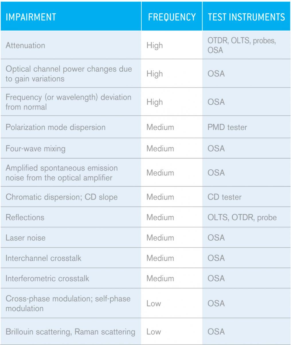
The information in Table 1 readily reveals that OSAs are the most versatile test instruments available, because they are capable of troubleshooting a wide range of issues in DWDM networks, greatly exceeding the capabilities of any other type of test set.
OSAs can also be used to predict bit-error-rate (BER) results at turn-up. Indeed, we know that the OSNR must be greater than 15 to 18 dB at the receiver to ensure proper signal detection. While a BER test usually takes over 24 hours, an OSNR test (IEC or in-band) takes only 5 minutes. If the first BER fails, a second BER test will be needed after the issue is fixed, resulting in a very lengthy turn-up procedure. A smarter and faster way to proceed, commonly used by operators in Europe, is to run a short 5-minute OSNR test before the BER test. If the OSNR result is higher than 15 to 18 dB at the receiver, the BER test will most likely pass. If the OSNR is lower than 15 to 18 dB, the technician can proceed directly to troubleshooting, thus saving a full >24h BER test that would have failed anyway.
Common OSA Measurements
While OSAs can be used to carry out a very wide range of measurements, the most common OSA measurements are listed in Table 2. For each type of measurement listed, we have indicated the type of OSA required.
Table 2. Common OSA measurements and related OSA types.
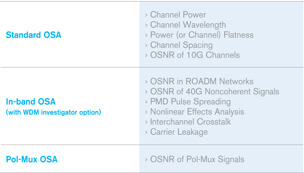
As can readily be seen, the added capability of a Pol-Mux OSA as compared to a standard or in-band OSA is that it is able to measure the OSNR of coherent signals. Now, let’s take a look at how and why OSNR measurement is different in Pol-Mux networks.
Why IEC and In-band OSNR Methods Fail in Coherent Networks
Note: This paragraph provides a brief overview of the IEC and in-band methods. For a more in-depth explanation, please refer to EXFO’s white papers on the subject of in-band OSNR.
The traditional method of measuring OSNR is defined in standard IEC 61280-2-9, and is known as the interpolation or out-of-band method.
Figure 1. IEC OSNR method.
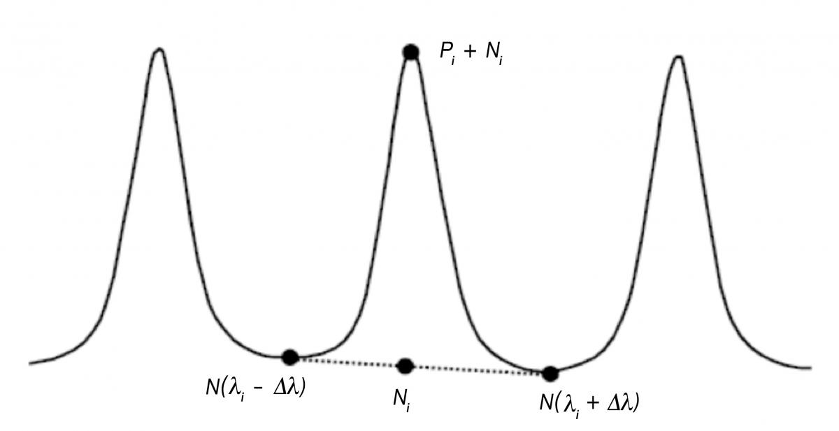
In a nutshell, this method consists of measuring the noise level at the midpoints between the channel of interest and its two adjacent neighbors (N(li-Δl) and N(li+Δl), and then computing the average of the two noise values to obtain Ni (Figure 1), thus performing a linear interpolation. The OSNR can then be calculated by dividing the signal power by this interpolated noise value. This method works well for networks up to 10 Gbits/s without any reconfigurable optical add/drop multiplexers (ROADMs). For 40 Gbit/s noncoherent networks, or networks that include ROADMs, a new OSNR approach, the in-band OSNR method, was introduced commercially back in 2009. We will now explore why these two methods are unsuitable for Pol-Mux signals.
Figure 2 shows 100G channels spaced at 50 GHz, a common spacing in modern networks. 40G/100G Pol-Mux signals are spectrally much wider than 10G, which means that they will overlap with neighboring signals (a phenomenon known as interchannel crosstalk). Accordingly, the midpoint between channels no longer consists only of noise, but rather signal plus noise. As such, when applied to 40G/100G Pol-Mux signals, the IEC method will lead to an overestimation of noise.
Figure 2. The IEC method fails with 40G/100G Pol-Mux signals.
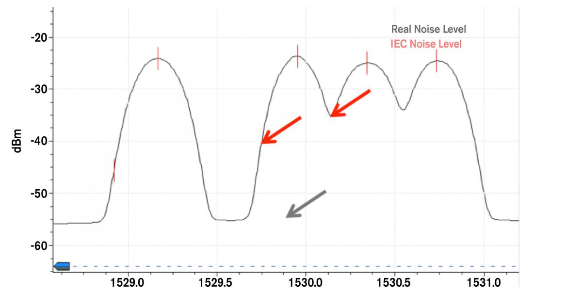
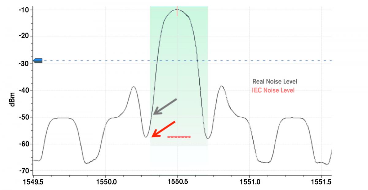
Figure 3 illustrates a 100G signal that has gone through a ROADM; the green area shows the channel bandwidth. Given that there are filters inside the ROADM, the noise at the midpoint between the channels will be carved (or filtered), leading to an underestimation of the noise level if the IEC method is used. Hence, ROADMs are yet another reason why the IEC method fails with coherent networks.
Figure 3. The IEC method fails with ROADM 40G/100G Pol-Mux networks.
So, we’ve proven that the IEC method fails with 40G/100G signals due to the width of the channels and to the presence of ROADMs, but what about in-band OSNR? The basic setup of an in-band OSA, as shown in Figure 4, consists of using a polarization controller followed by a polarization beam splitter. For non Pol-Mux signals, given that the signal is polarized and that the noise is unpolarized, adjustments to the polarization controller will change the proportion of signal split into each of the two branches, SOP-1 and SOP-2. To compute the in-band OSNR, complex algorithms can then be applied to the OSA traces found in branches 1 and 2.
Figure 4. In-band OSA setup.

For Pol-Mux signals, in-band approaches such as polarization or EXFO’s WDM-Aware will not work, because the signal appears unpolarized due to the fact that it consists of two orthogonal polarizations. The ITU-T Recommendation G.697 regarding such in-band methods states the following: “For a polarized multiplexed signal, there is a separate signal on each of the two orthogonal polarizations, so it is not possible to extinguish the signal using a polarization beam splitter. As such, it is not possible to use this method of OSNR measurement for these signals.”
So, both the IEC and in-band methods fail with OSNR measurements of 40G/100G Pol-Mux signals, thereby requiring a third method, called Pol-Mux OSNR, and the use of a Pol-Mux OSA.
EXFO’s POL-MUX OSA: COMMISSIONING ASSISTANT
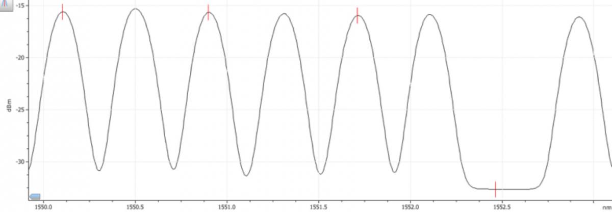
The commissioning assistant is a new feature in EXFO’s Pol-Mux OSA. This tool is perfect for Pol-Mux OSNR measurement during turn-up (especially in mesh networks), and is based on the channel shutdown method, which provides very accurate ASE OSNR measurements. To utilize the commissioning assistant, the user must first take a measurement at the receiver with all of the channels turned on (as shown in Figure 5), and then acquire a series of traces that have each been taken with one channel turned off (as shown in Figure 6). The commissioning assistant therefore requires a total of m+1 traces, where m represents the number of channels. The Pol-Mux OSA then performs the Pol-Mux OSNR calculations via a user-friendly wizard.
Figure 5. Trace with all channels on, ready for Pol-Mux OSNR calculation with the commissioning assistant
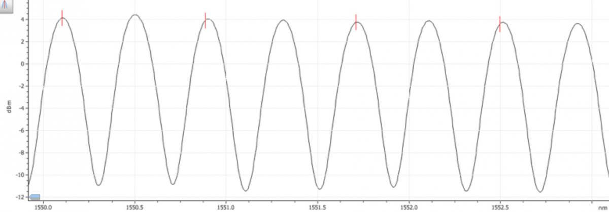
Figure 6. Trace with channel number 7 turned off, ready for Pol-Mux OSNR calculation with the commissioning assistant
In theory, a user who has all of the required m+1 traces can perform these calculations manually using the markers of the OSA; however, this procedure is long and tedious. In fact, there are several benefits to using the commissioning assistant over the manual method, including:
1. Time savings: With the manual method, the user has to properly position the markers on the OSA trace, note the relevant powers, and then enter the value in Excel or whatever tool is being used to perform the calculations, all of which is very time-consuming. The commissioning assistant, on the other hand, performs the same tasks with just a few clicks, saving several hours of computing in the case of a single trace with many channels.
2. Reduced human errors: Correctly positioning the markers in the OSA, entering the values in Excel, and ensuring that the correct noise level corresponds with the correct signal power are all tasks involving potential sources of error. The commissioning assistant prevents such errors from occurring.
3. Facilitated reporting: Use of the commissioning assistant enables users to obtain clean, clear reports containing all relevant information, e.g., signal power, OSNR and trace. However, when the manual method is used, signal power and OSNR information is stored in various different reports and locations, which is much less practical!
Although primarily designed for Pol-Mux OSNR calculation, the commissioning assistant can also be used to automate OSNR calculations based on the channel turn-off method for any type of signal (10G, noncoherent 40G, etc.). However, EXFO recommends using the in-band OSNR for noncoherent 40G signals and ROADM networks.
STANDARDS-BASED POL-MUX OSNR MEASUREMENTS WITH EXFO’S POL-MUX OSA
As of Winter 2014, there are two standards providing relevant guidelines for OSNR measurements of Pol-Mux signals, i.e., the China Communications Standards Association (CCSA) YD/T 2147-2010 and the IEC 61282-10 (draft), both of which are explained below. These methods are implemented in EXFO’s commissioning assistant, and all calculations are automatic.
The Chinese CCSA YD/T 2147-2010 standard recommends calculating Pol-Mux OSNR as follows:
Pol-Mux OSNR = 10log10 ((P-N)/(n/2))
Where, for a 50 GHz channel:
P = integrated power (Signal + Noise) over the 0.4 nm channel bandwidth
N = integrated power (Noise) over 0.4 nm bandwidth
n = integrated power (Noise) inside 0.2 nm, then normalized to 0.1 nm
First, with all channels on (as shown in Figure 5), the P of a specific channel is determined by measuring the integrated power in the spectral range of the channel bandwidth. For instance, on a 50 GHz grid, that means a spectral range of ±0.2 nm on either side of the signal central wavelength is considered. Given that P represents the sum of the signal power plus the noise power in the channel bandwidth, in order to obtain the signal power only, it is necessary to subtract the noise power in the channel bandwidth (N) from P. Therefore, N is obtained by measuring the integrated power in the spectral range within ±0.2 nm (50 GHz case) on either side of the signal central wavelength, on the trace where that specific channel is turned off (for example, channel 7 in Figure 6). Next, the n value is again determined from that same trace with that specific channel turned off (as per Figure 6), but this time by measuring the total power in the spectral range within ±0.1 nm on either side of the channel central wavelength. It should be emphasized that within the context of today’s high modulation rates, the 0.2 nm range is considered to be more representative of the noise level than a 0.1 nm range. However, the noise power is then normalized to a 0.1 nm, given that it is common practice to report OSNR figures in a 0.1 nm reference noise bandwidth. Inputing P, N and n into the equation makes it possible to calculate the Pol-Mux OSNR value. The Pol-Mux OSA automatically carries out that same procedure for all of the channels for which a turned-off trace is available.
The IEC 61282-12 recommendation has not yet reached final approval stage, and therefore the calculation might differ slightly from that presented in this document. The standard defines OSNR as the “spectrally integrated ratio of time-averaged spectral power density of a signal to the spectral power density of the amplified spontaneous emission (ASE), normalized to a chosen reference bandwidth and expressed in dB. The OSNR expressed in dB is 10log(R), with R calculated as:
s(l) is the time-averaged signal spectral power density, not including ASE, expressed in W/nm
r(l) is the ASE spectral power density, independent of polarization, expressed in W/nm
Br is the reference bandwidth expressed in nm (usually 0.1 nm if not otherwise stated)
and the integration range in nm from l1 to l2 is chosen to include the total signal spectrum.”
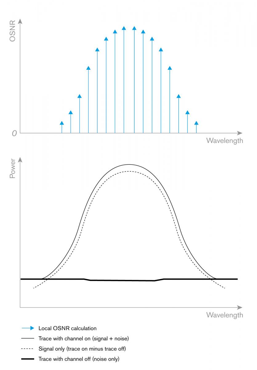
The integral of the R value shown above is similar to calculating the OSNR value locally for a very small (infinitesimal) spectral range, and then calculating the sum of all these local OSNR values for the whole channel bandwidth, and subsequently normalizing this sum to 0.1 nm.
In addition, Clause 8, entitled “Guidelines for using this definition,” of the IEC 61282-12 recommendation states that: “It is the intention of this technical report to provide a mathematical definition of OSNR and not to prescribe a measurement method.” In order to comply with this standard, EXFO has therefore chosen to implement an approach in its commissioning assistant which makes use of the same combination of traces as the Chinese standard, i.e., one trace with all channels on, and a series of m traces, each of which has one channel off (m = number of channels). Figure 7 shows this situation for a specific channel. r(l) can be readily determined from the trace with the channel off, while s(l) can be calculated by subtracting the noise power at a given wavelength (trace with channel off) from the Signal + Noise sum at that same wavelength (trace with channel on). Next, for each infinitesimal spectral range, the local OSNR (or the r/s ratio) is computed, as shown by the blue arrows in Figure 7. The integral is finally carried out from l1 to l2, which is equal to the channel bandwidth, i.e., 0.4 nm in the case of a 50 GHz grid.
Figure 7. EXFO’s implementation of IEC 61282-12 standard for Pol-Mux OSNR measurements.
Conclusion
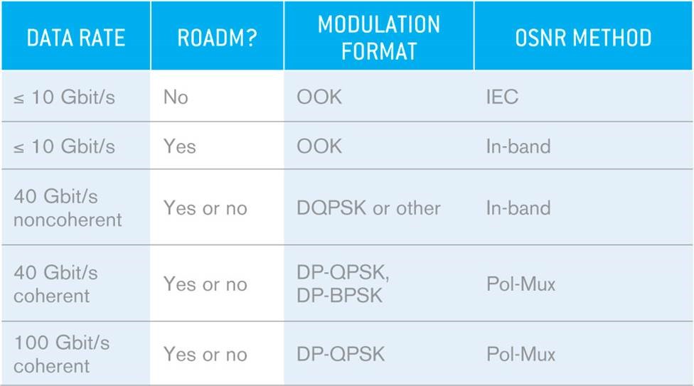
In this paper we have shown that, based on the most common impairments identified by the ITU, an OSA is the most versatile test instrument available on the market. We then demonstrated that the current available methods for OSNR measurement, i.e., the IEC and in-band methods, do not work for Pol-Mux signals, which require a third method called Pol-Mux OSNR called Pol-Mux OSNR (see Figure 8). EXFO’s new Pol-Mux OSA is the first third-party instrument to offer coherent OSNR measurements, and consists of a user-friendly tool referred to as the commissioning assistant. Compared to the manual procedure for OSNR measurements with the channel turnoff method, this new Pol-Mux OSA enables users to save time, reduces the risk of human errors, and facilitates reporting.
Figure 8. OSNR method for different types of networks.
