By Jennifer Cline and David Hessong
The Cisco Visual Networking Index predicts that Internet Protocol (IP) traffic will increase at a compound annual growth rate (CAGR) of 22 percent from 2015 to 2020, driven by explosive growth in wireless and mobile devices. All of that data is translating to growth in both enterprise and cloud data centres. This growth explains why data centres are often the earliest adopters of the fastest network speeds and are consistently searching for solutions that preserve rack and floor space. Just a few years ago, a density revolution occurred in the structured-cabling world, doubling the density of passive data centre optical hardware to 288 fibre ports of either LC or MTP connectors in a 4U housing. This increase has now carried over to the switching side, where deployment of a port breakout configuration can as much as triple the port capacity of a switch card operating in a 10G or 25G network.
To understand how port breakout deployments work we must first understand the transceivers that the network is using. The dominant high-density 1G and 10G transceiver is the enhanced small form-factor pluggable (SFP+). As speeds have increased to 40G, the quad small form-factor pluggable (QSFP) has become the high-density transceiver of choice. In parallel 40G applications, four 10G coppers traces run into the back of the QSFP transceiver, and four discrete 10G optics send light out of the front of the transceiver over eight fibres. This design allows a 40G transceiver to operate as either four discrete 10G links or one native 40G link.
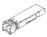
Figure 1: SFP+ transceiver
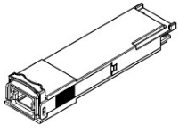
Figure 2: QSFP transceiver
The first and most obvious benefit of running a 10G network over parallel ports is the density that’s achievable over a single switch line card. High-density SFP+ switch line cards typically come with a maximum of 48 ports. Today, however, you can purchase a high-density QSFP line card with 36 ports. If it operates in breakout mode, each of the 40G ports can serve as four discrete 10G ports, tripling the line card capacity to 144x10G ports on a single line card. Figures 3 and 4 show this configuration.
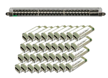
Figure 3: 48x10G SFP+ line card.
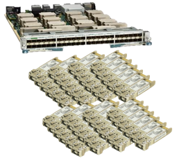
Figure 4: 36x40G QSFP line card
As previously mentioned, a 36-port 40G QSFP line card in port-breakout mode supports a total of 144x10G links, as each 40G port acts as 4x10G links. To support this same number of 10G links with traditional SFP+ transceivers, three 48-port SFP+ line cards would be necessary, as Figure 5 shows. As the volume of 10G port-capacity requirements increase, this effect continues to grow. For every chassis fully loaded with 40G line cards operating in 10G port-breakout mode, three chassis would be necessary if the network were built with traditional 48-port 10G SFP+ line cards. By deploying 40G line cards, the occupied space in the data centre drops considerably.
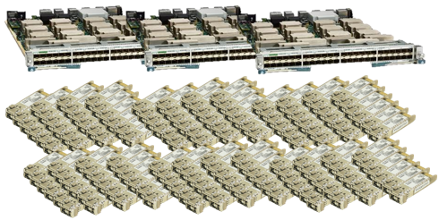
Figure 5: SFP+ line cards and transceivers to support 144x10G links.
In addition to space savings, which is critical in the data centre, economic savings in both capex and opex become available. Let’s first focus on capex savings by looking at the costs to deploy a 10G network with standard SFP+ high-density line cards and the cost to deploy a 10G network using high-density QSFP line cards.
We evaluated a scenario with an eight-slot chassis fully populated with 36-port QSFP line cards. The line cards were populated with 40G parallel optical transceivers operating in breakout mode for a total chassis port count of 1,152x10G ports. Achieving the equivalent 10G port capacity using 10G SFP+ line cards requires a total of three eight-slot chassis with 48-port line cards. The cost comparison in Figure 6 includes the cost of the switch chassis, the line cards and the associated transceivers, using standard list pricing for all components. The chassis cost includes the required power supplies, fan trays, supervisors, system controller and fabric modules. As the number of chassis needed to support the 10G port density increases when using SFP+ transceivers, the number of these additional components increases as well. As a result, the study shows that on a per-port basis, deploying discrete 10G ports costs almost 85 per cent more compared with deploying 40G ports in breakout mode for multimode applications. Figures 6 and 7 show the results in graphical and tabular form, respectively.
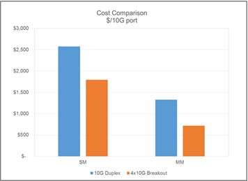
Figure 6: Cost comparison
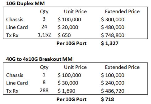
Figure 7: Cost comparison, includes the chassis, power supplies and cords, system controller, fan trays, and fabric modules
Now let’s evaluate the opex benefits. To begin, most vendors’ 40G and 10G switch chassis and line cards have similar power requirements. A reduction of approximately 67 per cent in required power and cooling comes from reducing the number of chassis and line cards by two-thirds, in addition to the space savings already discussed. And, as an added benefit, we can save the additional power required to operate the transceivers. The data in Figure 8 show greater than 60 per cent transceiver power savings when deploying multimode breakout configurations.
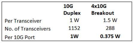
Figure 8: Transceiver power comparison
In addition to the benefits in space savings and cost, data centre operators can gain an additional benefit on Day 2 when increasing network speeds from a high-density 10G (or 25G) architecture to a native 40G (or 100G) network. As the network moves from breakout 10G (or 25G) to native 40G (or 100G), the existing 40/100G optics and line cards operating in breakout mode can continue to handle the native 40/100G links. This approach allows for two speed generations out of the switches, line cards and associated parallel optic transceivers.
Because parallel optic transceivers operate over eight fibres, it’s important to consider how to design the data centre structured cabling to support breakout mode. Recommended designs include solutions that employ Base-8 MTP connectivity for the optical infrastructure to optimise fibre utilisation and port mapping. As Figures 9a, 9b and 9c show, deploying connectivity with an eight-fibre MTP connector interface provides a simple and optimised solution to breakout to four LC duplex ports for patching to 10G equipment ports.
Figures 9a and 9b depict structured cabling designs in which a dedicated cabling backbone is installed between the equipment with 40/100G and 10/25G ports. Figure 9a is useful when all four of the 10/25G ports are co-located in a single equipment unit, whereas the layout in Figure 9b is helpful when the patch cords from the structured cabling must reach different equipment ports in a cabinet. Figure 9c, however, offers the most flexibility for the data centre structured cabling by breaking out the 40G (MTP) ports into LC duplex ports at a cross-connect location. Using a cross-connect implementation in a central patching area, any 10/25G breakout port from the 40/100G switch can be patched to any piece of equipment requiring a 10/25G link.
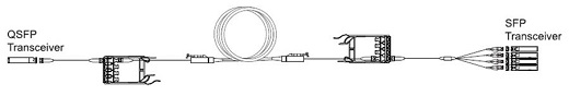
Figure 9a: Port breakout using an eight-fibre harness
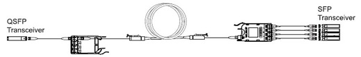
Figure 9b: Port breakout using an eight-fibre module
'
Figure 9c: Port breakout with a cross-connect, using an eight-fibre port-breakout module
All of the values in this article, plus additional networking benefits in spine-and-leaf architectures not covered in detail, help to explain the popularity of parallel optic transceivers for high-density 10G and 25G networks. Although our focus has been on Ethernet networks in the data centre, the same approach works in storage-area networks (SANs) over Fibre Channel (FC). SAN director line cards are available with parallel optics QSFP transceivers operating as 4x16G-FC, enabling high-density 16G-FC SAN fabrics. The benefits explain why both Ethernet and Fibre Channel have eight-fibre parallel optics choices for all existing speeds on their roadmaps, including 400G and beyond. When evaluating options to deploy 10G or 25G, network managers should evaluate breaking out of parallel ports owing to the networking and economic advantages it provides.
--
Jennifer Cline is the Plug & Play systems product-line manager for Corning, where she is responsible for managing the company’s MTP data center solutions. She has previously held positions in Engineering Services, Marketing, Field Sales and Market Development. Jennifer is a BICSI member and holds both CDD and CDCDP certifications. She received a Bachelor of Science degree in mechanical engineering from North Carolina State University.
David Hessong is currently the manager of global data center market development for Corning. During his career with the company, he has held positions in Engineering Services, Product Line Management and Market Development. David has published numerous industry articles and has contributed to several technical-conference proceedings. He has taught classes and seminars on data centers and system design across the United States and Canada. David received a Bachelor of Science degree in chemical engineering from North Carolina State University and a master’s degree in business administration from Indiana University’s Kelly School of Business.
